


Buy the PCB:
DOCUMENTS:
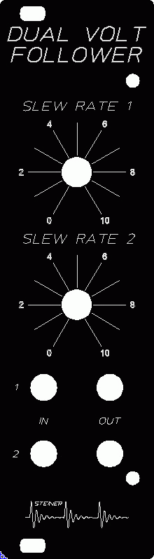
FUNCTION:
This module produces a glide, or slew between two voltages. The original Steiner keyboard had a portamento built into it, and this module was made to add this capability to arbitrary control voltages.
From the Synthasystem manual:
The Voltage Follower does the same thing for control voltages that the portamento does to keyboard voltages. it requires as an input the output of a control voltage source, such as the Sample and Hold or the Sequencer, etc.
The output of the Sample and Hold, for example, could be fed into the Voltage Follower input jack and taken out of the output jack. With the Slew Rate knob all the way CCW, the voltage at the output jacks will follow the input voltage simultaneously. As the slew gets slower.
If the voltage from the voltage follower, for example, is used to control the frequency of a VCO, then VCO will glide from one pitch to another at a slower rate as the Slew Rate knob is turned clockwise.
USE:
Inputs/Outputs:
This module has two voltage followers and each has one input and one output.
Knobs:
This module has one Slew Rate knob for each voltage follower. It adjusts the time to rise or fall between two voltages.
GENERAL CONNECTIONS:
Hooking it up is pretty simple. Connect a control voltage, like from a keyboard, sequencer, EG, Sample and Hold, etc. Set the Slew Rate knob to give the desired effect.
COMPONENT SELECTION:
Resistors:
This module was originally built with carbon core, 5% resistors with one or two 1% metal film resistors. So, you have a wide range of options here. I recommend using 1% tolerance, metal film resistors everywhere.
Capacitors:
There are probably a billion different ceramic capacitors at a place like Mouser. Pick a capacitor that can fit the hole easily, typically 0.1 inch on centers.
Pick good quality electrolytics where designated.
ICs:
LM741s for op amps.
Diodes:
Nothing special, 1N4001s, and standard LEDs are fine.
Pots:
Your choice for your panel. If you use the panel I laid out, the holes and spacing will work for the Alpha 12 and 16mm pots. You can probably use nicer BTI, Bourns, etc. 9mm pots with “pot chiclets”
Trimmers:
Use good trimmers, please. A good Bourns multi-turn trimmer like Bourns 3296Y series will fit the pad layout and work well.
Jacks:
For the panel I laid out, a good 3.5mm or 1/8 inch jack will work. I use the Switchcraft 42A Tini-Jax true 1/8 inch jack. These are switched jacks and they work with 1/8 inch plugs and 3.5 mm plugs.
BUILD NOTES:
Soldering:
I assume you know the basics of soldering. I like to insert the low lying parts first, like resistors, diodes, etc. After these, I install the IC sockets. Next capacitors, transistors, connectors. Use a good solder, either an organic flux, which you should wash regularly, or a no-wash flux.
Take a break every so often, wash off the flux if you are using a flux which required cleaning. Double and triple check orientations, pins, and solder joints.
Power Supply Regulation/Filtering:
Some additional comments here. These modules are tested to run on +/-12 VDC. The original power supply in the Synthasystem was +12/-10 VDC due to how Nyle designed the -10 volt section of the power supply, not for any magical requirement to have -10 volts.
The power/regulation section has 2 voltage regulators on it which can be set to +12/-10 (or +/-12 volts) depending on your needs. If you are coming from +/-15 volts, you need both regulators and you may as well set one to -10 volts.
If you are coming from +/-12 volts, technically you don’t need the regulators, but if you want, install the negative one and set it to -10 volts. The LEDs are not strictly needed. They are there to establish a base current draw so the regulators will work.
Important… if you don’t install the regulators, you have to install a jumper between pins 2 and 3 as shown on the Power/Regulation PCB or you won’t get power.
COMPONENT PLACEMENT:
Mounting:
This PCB has four holes to allow flexible mounting configurations.
PANEL NOTES:
There is nothing too special. I suggest using connectors on the PCB and jacks on the flying wires. The spacing and holes are setup for Alpha 16 mm or 12 mm pots. The jack holes are 0.25 inch in diameter.