


The page is not all the way finished, but almost. Read it and don’t hesitate to email with questions.
Buy the PCB set:
There are two versions. One works with a smaller Alpha pot footprint, an Alpha RV120F series (make sure you get PCB pins, not solder lugs), 12 mm body diameter. The other works with a larger Alpha pot footprint, RV16AF series, 16mm pot body diameter.
Both PCB designs work with a Bourns or equivalent pot.
Be sure to buy the set that will work with the pots you want to use.
The PCBs are sold in sets of four PCBs each. Don’t order “4” unless you want to build four complete mixers :)
INITIAL COMMENTS:
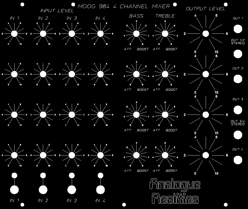
There are also two panel designs, one with pot holes for the Alpha pots, one with holes for the Bourns pots.
IMPORTANT: YOU WILL SEE TWO POTS IN PARALLEL FOR EACH POT. This does not mean you need two pots in parallel. I did it that way so I could more easily have two different footprints on the PCB layout. Please don’t try to install two pots, really, please don’t…
DOCUMENTS:
984 4 Channel Mixer document package with schematics, PCB layouts, and panel designs.
FUNCTION:
I recommend looking at the Moog Archives web site for more information. In essence, this is a four channel matrix mixer with bass and treble controls. The bass and treble will both amplify and attenuate highs and lows. It also has an overall gain of 1.25. I also highly recommend Dave Brown’s web site where he goes through a restoration of a Moog™ modular system including a 984 mixer.
USE:
I really like this mixer. You can have four separate mix variations for the four inputs. You can combine two of the channels for a stereo output (On my 914 FFB page, I added separate even and odd cell outputs so you can create a pseudo stereo image effect, a la Yves Usson’s idea, perfect to feed into this mixer for a final mix). You can add a little punch to the highs and lows or mellow a signal that is overly bright or heavy on the low end. It’s just a very versatile module anywhere in the signal path you use it. This mixer is simply great for a final output mix. It is AC coupled so that it is not suitable for CV mixing (see the CP3 page here for a DC coupled mixer with gain).
Inputs/Outputs:
Four inputs for audio. Four outputs for the resulting audio mix.
Knobs:
I used a typical Moog’ish knob. The output levels on my panel are set up for a larger knob, but use what seems best for your panel and system.
GENERAL CONNECTIONS:
This is a matrix mixer so that the four inputs can be combined and sent to any/all of the four outputs. The column of pots above each input determines how much of that input is fed into each row of outputs.
COMPONENT SELECTION:
See the Component Notes page for more information.
Resistors:
Use good ones to keep noise down, or use the original carbon, 5% if you want to be “authentic”.
Capacitors:
Nothing special. Use a decent ceramic, electrolytic or tantalum at least 25 volts.
The 80uF electrolytic is a hard one. Any value reasonably close is fine. 75uF to 85uF should work. 80uF are available, but expensive. There are reasonably priced 82uF electrolytics at Mouser. The pin spacing should accommodate most electrolytics in the 75uF to 85uF range.
In photographs from Dave Brown’s site, I noted that Moog used a 400uF electrolytic capacitor instead of an 80uF. Because of that, I used a 400uF, 25 volt electrolytic here; on my schematic, C113. I think it’s really just acting to add filtering to the negative rail voltage.
Transistors:
This design specifies the original Moog™ values, 2N2926. I got mine at Cricklewood Electronics. I think most any low noise small signal transistor should work, just watch the pinouts. They are clearly marked on the PCB.
Diodes:
Nothing special 1N4148 and 1N4001.
Pots:
Get good pots. Look at the pin spacing and pick the PCB layout that will match the pots you want. Both PCB designs work with Bourns PCB mounted pots. The Big Alpha PCBs work with the RV16AF series with a 16mm diameter pot housing. The Small Alpha works with the RV120F series with a 12mm diameter housing.
Log versus linear. I experimented with the Moog specified pots, and also with using linear instead of log pots. In the end, I liked using the type of pot specified by Moog.
The resistance of the input pots and output pots don’t matter too much since they are only voltage dividers, but don’t use smaller than 25k on the input and not bigger than the 5k on the output.
Jacks:
Use good jacks that match you system. I used 1/8 inch Switchcraft “tini-jax” and Switchcraft 1/4 inch so it works with my Steiner stuff and full size modules.
BUILD NOTES:
Soldering:
I assume you know the basics of soldering. I like to insert the low lying parts first, like resistors, diodes, etc. After these, I install the IC sockets. Next capacitors, transistors, connectors. Use a good solder, either an organic flux, which you should wash regularly, or a no-wash flux.
Take a break every so often, wash off the flux if you are using a flux which required cleaning. Double and triple check orientations, pins, and solder joints.
Power Supply Regulation/Filtering:
The design shows 4 tantalum capacitors in the power supply. Two before the regulators and two after. If you are using a +/- 12 volt main, just use the negative regulator to get -6 volts and use both polarized capacitors. Omit the positive regulator and install a jumper between the IN and OUT pins. Just use one of the polarized capacitors. These can also be 10uF (ten uF) electrolytic capacitors instead of 1uF (one uF) tantalums.
PANEL NOTES:
There are two panel layouts. The only difference is the hole size. One fits the Alpha pots, either series. The other fits the Bourns. You can certainly change the size to be what ever you want.
Each panel design has a groove machined on the back side of the panel and notched corners so you can bend the panel ends inward to more faithfully match the original Moog™ design. Modify these panels to suit your needs. You are welcome to delete my logo and insert whatever you want.
I also have holes for 1/8 inch “tini-jax” (or 3.5mm jacks) and 1/4 inch jacks for the inputs. I use both in my system and wanted to be able to use both without having to convert jack size. You can easily delete the small jack holes if you want to. The output jacks are 1/4 inch. You will need to wire the jacks by hand to use both the mono and stereo outputs.