


Build Photos:
Carsten Inductor version:
Here are a few photos of my build. Note that these are the last prototype PCBs and the connectors are not ideally mounted, in particular on the bottom filter cell PCB and on the I/O PCB. The production PCBs make it a little easier to use right angle connectors on the bottom of the PCB and give more clearance on the I/O PCB. These are from my build using Carsten’s inductors. These do not illustrate the corrections from the main page. The capacitors for the LP and HP need to be swapped and the corrections to the I/O PCB need to be made.


CineMag Inductor Version:
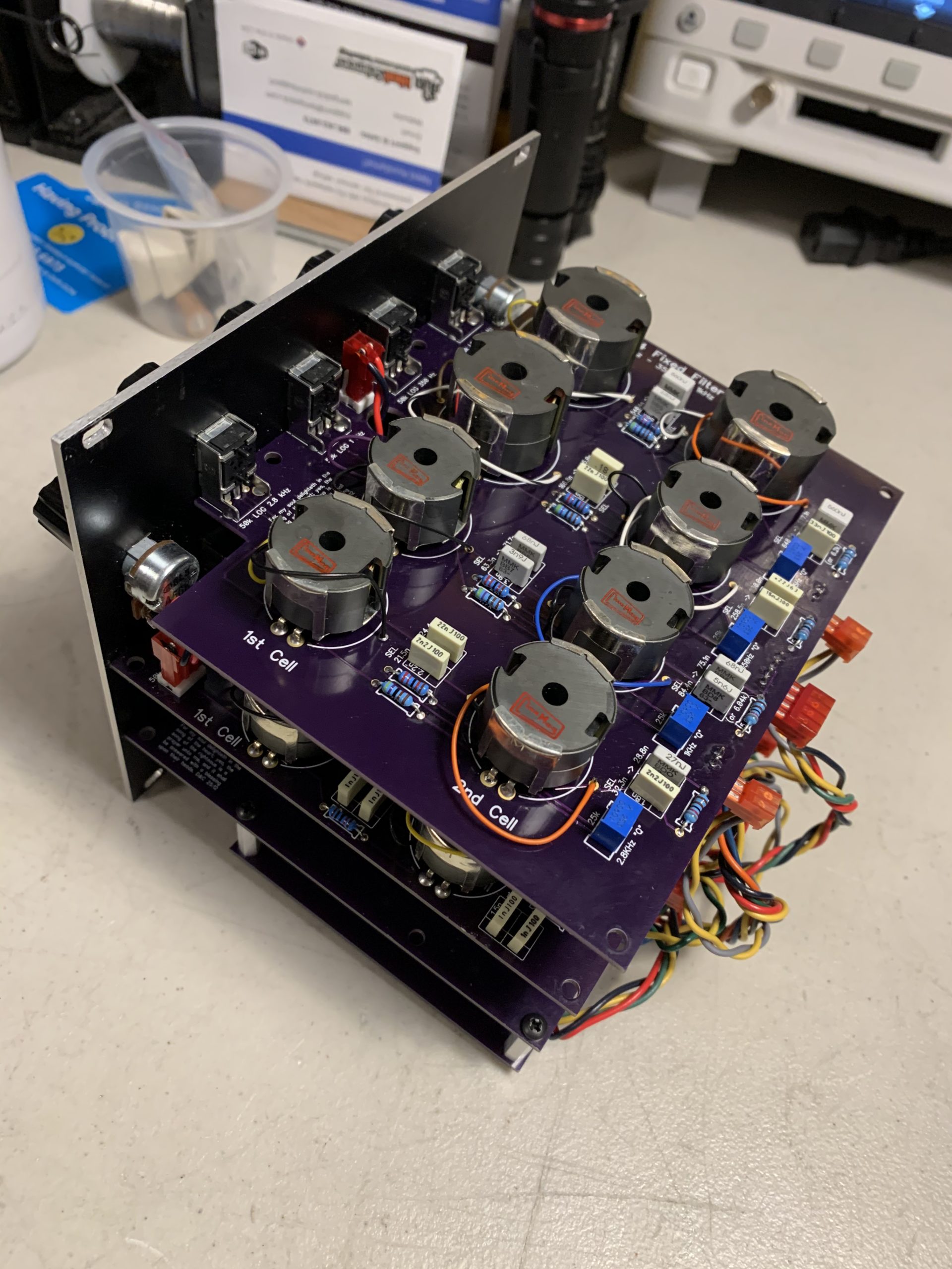
The following show the latest version using the CineMag Inductors. All the corrections noted on the main build page have been made. This version has replaced the one with Carsten’s inductors in my system.

Completed PCBs with Cinemag inductors. Note, I have the original capacitor values installed for the LP and HP cells. The I/O PCB is correct except for an experiment with the series capacitor to the output amplifier. You’ll see an electrolytic capacitor where a 0.1uF non-polarized capacitor should be near the feedback resistors. The other changes are there.

Here is one capacitor pair for the HP cell. The other pair should be the same. two 1.0nF capacitors in parallel. This applies to all versions, GIC and inductor.

Here is one capacitor pair for the LP cell. The other pair should be the same. a 1.0uF and a 0.22uF in parallel. This only applies to the inductor versions, both Carsten and CineMag.

This is a shot of the corrections to the IO PCB. See the jumpers and removed resistors center and top center, and the 2 220k feedback resistors, lower right. This applies to all versions.
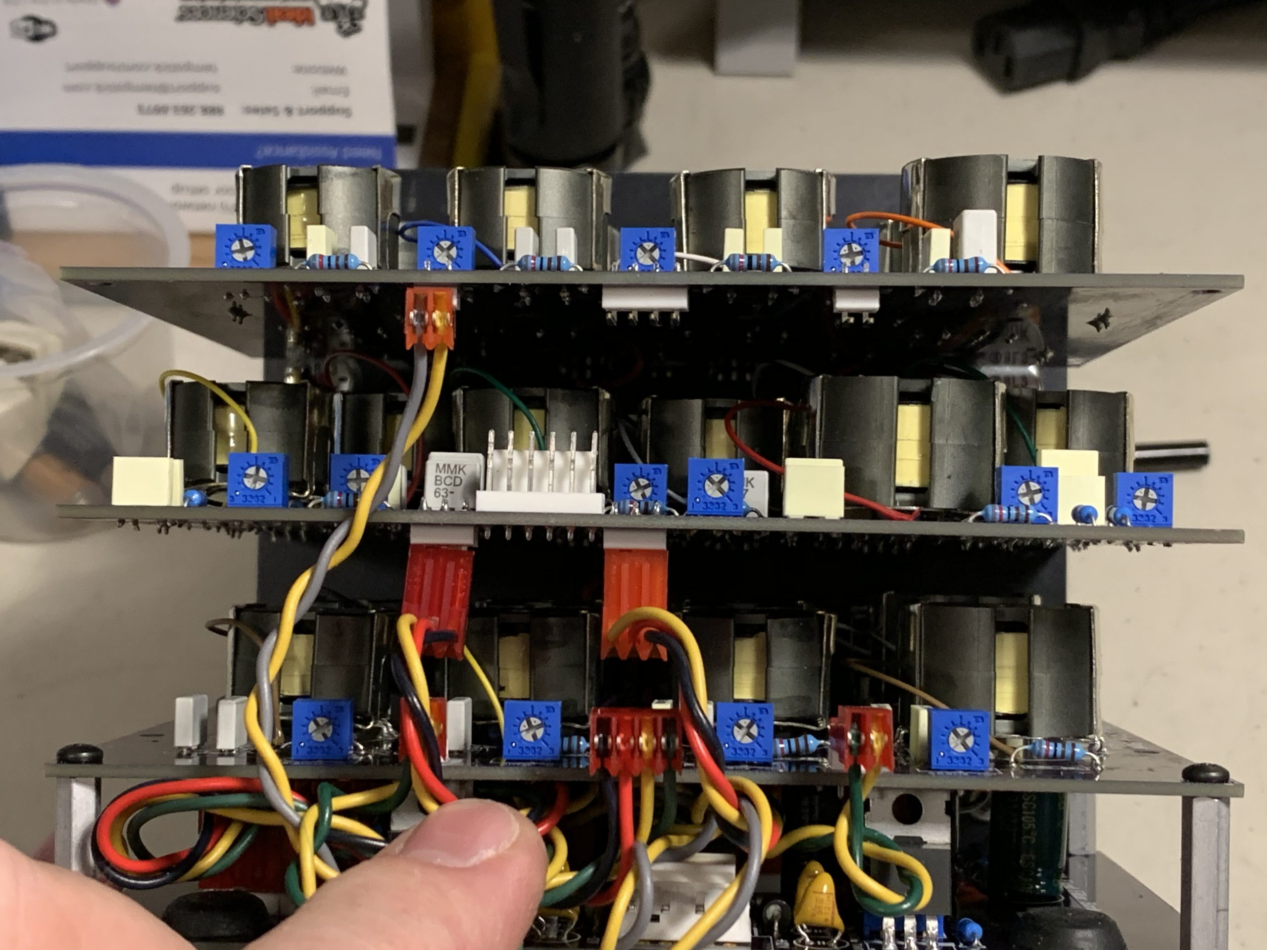
This shows the position of all the trimmers when I was done. Note that on the middle PCB, left side, HP trimmer I used “W” type. The indicating arrow is rotated 180 degrees as compared to a more standard “X” type. This means that mid-span the indicator points down. In other words, 12:00 is pointing straight down. I did this to make the CW rotation increase the “Q”. See the notes for more.
View of the top corner of the PCBs.

Corner view of the connectors and the 1.0nF capacitors in the HP cell.

Back view of the connectors.

The HP and 4kHz trimmers illustrating the difference between an “X” type (4kHz) and “W” type (HP) trimmer.