


Buy the PCB:

DOCUMENTS:
FUNCTION:
Nyle named this module a Voltage Controlled Function Generator. I think that is a fair and accurate name. It’s also a voltage Controlled Oscillator.
This module produces an oscillating signal whose frequency is based on a voltage input. Typically, this is an audible tone, but this module can oscillate from well below hearing to well above. The control voltage input is typically tuned to a 1 volt/octave scale. Four waveforms are available, Sine, Triangle, Sawtooth, and Pulse. These four outputs are available at the same time. This module has a very wide useable frequency range from well below audible as a Low Frequency Oscillator to above hearing without re-tuning. Nyle really outdid himself on this module. Very unique and I will say I think it has the best sine wave I’ve heard.
From the Synthasystem manual (note some of the details don’t apply to the re-issue module):
Each voltage controlled oscillator (V.C.O.) is identical except for the number of available waveforms that each produces. To avoid repetition we will describe the operation of the type A oscillator shown above, which produces all four waveforms. each waveform is available at two parallel output jacks and each waveform and each waveform has a separate amplitude level pot. Example: Sine wave amplitude is controlled with control knob #2 (Figure #11) and is fed to two output jacks in parallel. Likewise for the triangle, sawtooth and pulse waveforms produced by this oscillator. The pulse waveform has an additional control for pulse width and an additional input jack for controlling pulse width. either of these can control the width of the pulse coming out the output jacks. With the pulse width all the way CCW, and no input at the PWM jack, the pulse waveform is symmetrical and thus a square wave.
The frequency (or pitch) is controlled with the Frequency adjust knob from less than 1/10 Hz (cycles per second) to greater than 20KHz and can be fine adjusted with the Fine Frequency knob. Frequency is also controlled by feeding control voltages in the VC input jacks. Frequency modulation is accomplished by feeding an A.C. signal (such as the output from an oscillator) into one of these jacks instead of a D.C. voltage.
Each oscillator has an input jack called phase reset. Any signal with a fast negative going edge, for example a sawtooth, square wave, or pulse, will reset the output waveform to a precise point whenever the negative edge occurs as shown in figure #11A. usually the input signal at jack is lower in frequency than the oscillator, and the oscillator tends to take on a pitch sensation of the lower frequency with the timbre changing as the osc frequency is varied. This also makes it possible to have one oscillator track at a harmonic of another with no beating whatsoever.
Here are the figures:


USE:
Inputs/Outputs:
This module has three fundamental inputs and four outputs:
- VC Inputs – These inputs accept a voltage input, typically between 0 and 10 volts. This can come from any source which provides a voltage output. VC3 Var Scale is an input which can be configured to respond to a different scale than the 1 volt/octave scale of the other two inputs.
- VC Width – This input accepts a voltage which dynamically changes the width of the pulse on the Pulse Output.
- Phase Reset – this input accepts a falling edge to reset the phase, or sync, the VCO output frequency to that of the signal at this input. A signal with a steep trailing edge works best, such as a pulse or a “ramp” type sawtooth wave.
- Waveform Outputs – The top row of jacks provide the waveform outputs according to the legend on the panel.
Knobs:
This module has 9 knobs; 4 for output levels, 1 frequency, 1 fine frequency, 1 pulse width, 1 v/Oct trim, 1 VC3 Scale.
- Four output level pots – These are attenuating controls to set the relative output levels of the 4 waveforms.
- Frequency – This sets the base frequency of the oscillator.
- Fine Frequency – This allows a fine adjustment of the base frequency.
- Pulse Width – This sets a base pulse width which is combined with the VC Width input.
- V/Oct trim – This front panel trimmer allows more convenient calibration of the V/Oct response. It is only used when re-calibration of this response is required. It may also be located on the PCB.
- VC 3 Scale – The third VC input can be configured to respond to a scale which is different than the scale of the other two inputs which is set with the V/Oct trimmer. This can be a regular potentiometer or a trimmer like the V/Oct trimmer depending on how the module is built and configured. It may be omitted or be on the PCB.
GENERAL CONNECTIONS:
VCOs are the main module for producing audio. A typical patch would connect a 1 volt per octave controller to one of the VC jacks like a keyboard. However, any source of voltage can control the pitch. Voltage sequencer, EG, another VCO or fixed oscillator, the output of the Sample & Hold, and on and on. Connect the output waveform to a a module that processes audio.
Any varying voltage can be use as a VC input and the output can drive any input that can handle the voltage.
- Envelope Generator
- Ribbon Controller
- Amplified microphone
- Wrap some resistive wire around a wood dowel, connect the ends to a power source, (make sure you have a common ground) take a wire and drag it across the wire like a potentiometer.
- Use the VC2 or VC3 in for a frequency modulation input.
- An accelerometer connected to your hand.
It’s only limited by your imagination.
The frequency range of this VCO makes it very useful as an LFO (Low Frequency Oscillator). You can use the output of one VCO to modulate the other.
The Phase Reset is, in more common jargon, a sync input. Use the Saw or Pulse output of one VCO to force a second VCO to oscillate at the same frequency. This is a nice way to combine the outputs of two VCOs and have them stay in tune. However, one of the consequences is the second VCO may reset (probably will reset) before a full cycle of its wave. This will add harmonic content and will (hopefully) make the resulting output more interesting and rich. You can detune the second, third, fourth, etc. sync’d VCO intentionally to emphasize this extra harmonic content
COMPONENT SELECTION:
Resistors:
This module was originally built with carbon core, 5% resistors with one or two 1% metal film resistors. So, you have a wide range of options here. I recommend using 1% tolerance, metal film resistors everywhere, but the critical resistors are R37 and R38, input summing resistors. These should ideally be hand matched or purchased to 0.1% tolerance to insure consistent response between the inputs.
In the Saw Core, R8, R14, R3, and R1 could be high quality, low temperature coefficient, RN55E series resistors, 0.1% to give the best stability and tracking.
The thermistor in this module should be a standard 1K 3000 to 3500 ppm part. Precision resistor sells them as do other sources like the Bridechamber, Magic Smoke, and others. It just has to span a long way, so make sure your part has sufficient lead length.
On Dave Brown’s ModularSynthesis website on this page, about half way down, he shows how he makes a 2k tempco from 2 SMD resistors, Digikey P68CDCT-ND 3300 PPM resistors. You could do something similar with one 1k resistor.
Capacitors:
There are probably a billion different ceramic capacitors at a place like Mouser. Pick a capacitor that can fit the hole easily, typically 0.1 inch on centers. For C2, pick a high quality, low leakage, temperature stable capacitor like a Polystyrene. The tolerance is not as important as the temperature stability. If you can’t find a polystyrene, use a polypropylene.
Electrolytics, on power regulation PCB, should be rated at 25 to 35 volts.
ICs:
The only ICs really are the LM741 OpAmps. There are many OpAmps with much better specs, but these ones will affect the sound to some degree. If you want a true re-release of a Steiner VCO, use the LM741 or equivalent. If you aren’t too worried about it, use a newer OpAmp. Just make sure it is a single OpAmp with the proper pinout. The offset null is not used.
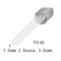
Transistors:
Discrete Transistors:
The original used 2N5172 NPN and 2N5138 PNP transistors. These are still available, but I could only find a “PN5138” which I think is the same transistor. In any event, you can use any standard NPN or PNP transistors and they should work.
There are three spots compatible with an SSM2210 monolithic NPN transistor pair. The only one which is critical is the exponential converter in the Sawtooth core. The other two can be any small signal NPN transistor matched or not. A matched pair won’t hurt which is why I laid it out to accept an SSM2210 or other monolithic pair. If you use the 2N5172s, I’m sorry, you will have to twist them since they don’t use the standard EBC pin order. It’s a bit of a pain, but can be done. Other small signal NPNs use the common EBC pin order and will fit without a problem.
The exponential pair should really be matched which means the Vbe of two transistors at the same temperature in the same circuit is the same within about 2 millivolts or better.
Either you need to hand match some NPNs, or you need to use a monolithic NPN pair. The SSM2210, or LS318 are good choices, but any small signal monolithic matched pair should work. Analog Devices has a new part, the MAT12 which should work, too.
Q3 is a PNP which is placed physically close to and in thermal contact with the matched NPN pair and it should be in thermal/mechanical contact with the NPN pair and thermistor. As another option (see more detail below) you can use a THAT340 which has a matched NPN pain and an matched PNP pair on the same chip. The PCB pinout will take this chip, too.
So, with that advice and help, in discussions with Nyle, he reminded me they only matched transistors for a short while and in later modules, they weren’t matched! So, if you want to be really authentic, don’t match any transistors. Just solder up a couple which look like they go together.
The NPN pair and PNP really, really do need to be in thermal/mechanical contact with each other and the tempco. For mine, I’m going to build at least one with hand matched discrete transistors since that is what I would have done in ’75.
See the Transistor Matching PCB page for more information and links.
There are two other SSM2210s on the schematic. You can use a monolithic pair, or hand matched pairs, but unmatched small signal transistors will work fine, too.
THAT340:
As an option, you can use a THAT340 which has an NPN and PNP monolithic pair. This saves the problem of hand matching, or trying to squish 3 transistors and a resistor together and keep them there. If you do this, DO NOT INSTALL Q3. I’ve warned you. If you do, you will have two transistors hooked up in parallel and I really don’t know what that will do. The THAT340 can be purchased at Mouser, P/N 887-340P14-U, THAT P/N 340P14-U.
Thermal contact:
Make sure whatever configuration you use for the exponential pair and Q3 that these three transistors and the thermistor are in good mechanical and thermal contact. Use a little heatsink grease to help conduct the heat and make up for very small gaps.
FET:
Originally, the Steiner modules used a 2N5163 JFET. In later modules, this was replaced with a 2N5246 JFET due to some quality problems with the 2N5163. The 2N5246s are still available and manufactured. Other JFETs will work here, too. I’ve tried some NTE equivalents for the 2N5163 which seemed to work fine. They are more expensive than the 2N5246s though and the 2N5246 is “vintage”. See the Component Notes pages for more information and sources.
Diodes:
Nothing special, 1N4148s are fine.
Pots:
Your choice for your panel. If you use the panel I laid out, the holes and spacing will work for the Alpha 12 and 16mm pots. You can probably use nicer BTI, Bourns, etc. 9mm pots with “pot chiclets”
Trimmers:
Use good trimmers, please, really on this PCB use good trimmers. A good Bourns multi-turn trimmer like Bourns 3296Y series will fit the pad layout and works well.
The original modules used single turn, carbon trimmers. You can get a Bourns model that will fit the pad pattern if you want to. They cost about as much as the nicer multi-turn pots, though. It’s a Bourns 3352H series has the appropriate pin spacing/configuration. The 3329H and 3329W series are sealed versions which will work, too.
For the panel mount trimmers, I made a little PCB chiclet like the ones above to make this easier. I suggest using a Bourns adapter, p/n H-83P. It has plastic 5/16 inch threads, so the hole is 0.3125 inches in diameter. It seems to work with any standard 3.4 inch multi-turn trimmer. Insert the trimmer and push it til it snaps into place.
Another option is a Vishay part p/n 006-1-0 or 006-1-1, or 006-1-2, or 006-1-3. It depends on what type of shaft you want to have. These have a smaller, metal bushing. A 0.22 inch hole works fine. They are a bit smaller than the Bourns and about 3 times as expensive. $5.00 compared to about $1.50. If you use this one, I’d also recommend getting the Vishay trimmer adjustment tool. It’s made to fit down the hole if you don’t buy the adapter with a shaft. No Vishay part number. Mouser p/n 594-8T000.
The Bourns trimmers which work are the 3006 series. Easy to find.
The Vishay trimmers which work are the model 43P 3/4″ 20 turn series. Easy to find.
Jacks:
For the panel I laid out, a good 3.5mm or 1/8 inch jack will work. I use the Switchcraft 42A Tini-Jax true 1/8 inch jack. These are switched jacks and they work with 1/8 inch plugs and 3.5 mm plugs.
BUILD NOTES:
Soldering:
I assume you know the basics of soldering. I like to insert the low lying parts first, like resistors, diodes, etc. After these, I install the IC sockets. Next capacitors, transistors, connectors. Use a good solder, either an organic flux, which you should wash regularly, or a no-wash flux.
Take a break every so often, wash off the flux if you are using a flux which required cleaning. Double and triple check orientations, pins, and solder joints.
Power Supply Regulation/Filtering:
This PCB requires the Power/Regulation daughter board. I did it this way to allow this PCB to be parallel to the front panel which allows it to mount in shallow cabinets.
See this page for details on this module.
For the sake of the VCO, you need to install the extra filtering capacitors and resistors. the VCO uses both the base +12/-10 volts from the mains and the extra filtered supplies.
R2 and R6 are 22 Ohm, C4 and C8 are 150uF electrolytics.
Connect all 5 pins between the power PCB and VCO.
Build this PCB first and get the regulators (if you use them) trimmed to +12/-10 volts.
Some additional comments here. These modules are tested to run on +/-12 VDC. The original power supply in the Synthasystem was +12/-10 VDC due to how Nyle designed the -10 volt section of the power supply, not for any magical requirement to have -10 volts.
With that said, the power/regulation PCB has 2 voltage regulators on it which can be set to +12/-10 (or +/-12 volts) depending on your needs. If you are coming from +/-15 volts, you need both regulators and you may as well set one to -10 volts.
If you are coming from +/-12 volts, technically you don’t need the regulators, but if you want, install the negative one and set it to -10 volts. When this board is not connected to the main VCO PCB, you have to have a minimal load in order for the regulators to regulate, that’s the purpose of the LEDs. you can install these for fun if you want, but are not needed if you don’t use the regulators.
Important… if you don’t install the regulators, you have to install a jumper between pins 2 and 3 as shown on the Power/Regulation PCB or you won’t get power to the VCO.
COMPONENT PLACEMENT:
The V/Oct and VC3 scale trimmers need some explanation. There are two mounting locations each for these two components. ONLY USE ONE OF THE TWO LOCATION FOR EACH TRIMMER. You have been warned.
Panel Mounted Trimmers:
The edge locations are for those who (like Nyle and me) want these trimmers accessible without removing the module and will run a panel mounted trim pot. If you do this, there are a couple of options I’ve found. First, Vishay/Spectrol makes an adapter to turn a 3/4 inch multi-turn trimmer into a panel mount. The panel hole should be 0.22 inches in diameter.
The Bourns has a 0.3125 inch thread, so the hole should be 0.32 give or take a bit.
If you use my panel, you will get two holes, the V/Oct drilled for the Bourns trimmer adapter 0.32 in, and the VC3 Scale drilled for an Alpha 12mm or 16mm pot, 0.2813 in (7.14 mm).
See the Component Notes page for more information and sources.
PCB Mounted Trimmers:
If you don’t want panel clutter, mount the appropriate trimmer at the location on the interior of the PCB and do not run a pot to the edge connectors.
Thermal Contact:
The exponential pair and Q3 need to be mounted such that all three are in mechanical and thermal contact with the tempco. Be creative here depending on what configuration you decide to build. Use a little heat sink grease to help make sure. I often use small zip ties to hold stuff like this together.
Mounting:
This PCB has four holes to allow flexible mounting configurations. The FPE Euro panel is setup to allow this PCB to be mounted parallel to the panel using some 3/4 to 1 inch (typical) standoffs. The mounting holes are connected to ground. The Power Regulation PCB will mount to this PCB using standoffs.
CALIBRATION:
There are a lot of trimmers on this PCB, and that is without apology. They aren’t really difficult to setup, but it will take a little time. You will need a good volt meter and an oscilloscope. Read through this entire section before you start. the V/Oct setup is similar to all VCOs, there are a lot of trimmers to set that other VCOs don’t have/
The Phase Sync, Sawtooth, Triangle, and Sine adjustments all interact and you may want to do them a couple of times until you get the desired results.
SAWTOOTH AND PHASE SYNC:
Phase Sync:
- First, set R52, Frequency Range, close to fully CW (clockwise) (if you don’t hear a sound, turn R52 more CW until you hear something). Set R33 or R36, the V/Oct Trimmer (whichever you chose to use) to mid point.
- Connect an oscilloscope to the saw output.
- Adjust R52 until you hear/see an output. Something in the hundreds of Hertz will be fine for now.
- Turn R39 Phase Sync clockwise (towards +12 volts) until the spike on the trailing edge disappears, then just a bit more. (you may also have to adjust R44 here to get the waveform into a useable range). This will also dramatically reduce or eliminate the little spike on the triangle wave, too. In practice, you should be able to eliminate this spike.
Sawtooth Offset:
Next, adjust the sawtooth offset to balance the waveform around 0 VDC, R44.
SQUARE/PULSE WAVE:
Pulse Width Minimum/Maximum:
Next, we will adjust the Pulse Width Minimum and Maximum.
- Set R28 toward the counterclockwise side, not necessarily full.
- Set R23 to mid point.
- Connect an oscilloscope to the Pulse output.
- Turn the Pulse Width knob fully counterclockwise. That is, ground the input. You want Q12 to be off. If you want, take a clip lead and short the base of Q12 to the emitter of Q12 to make sure it is off.
- Looking at the scope, turn R28, Maximum Width, until you get a very narrow pulse. No specific width, just what you want.
- Remove the clip lead on Q12 if you put it on.
- Turn the Pulse Width knob fully clockwise. As a check, you should have about 5 volts or a little more on on the wiper.
- Adjust R23 to get a small pulse on the output. If you want, you could adjust R23 to get a 50% duty cycle square wave.
If you are having trouble getting a narrow pulse with R23, you can vary the value of R21 so that you measure at least 5 volts on the wiper at full clockwise rotation of the Pulse Width knob, R25.
You might also want to adjust these trimmers to give a 50% duty cycle at some particular spot on the PW control, too. Maybe use a pot with a detent in the middle and set these trimmers to give you a 50% duty cycle at the detent spot.
TRIANGLE:
Triangle Shape:
Lets move on to the triangle wave.
- Connect a scope to the triangle output.
- Turn the offset to mid point, or to where you can see the triangle wave. We’ll come back to this trimmer.
- You should have installed R58 to start with, and a jumper at R67.
- Adjust R58 until the wave looks like a triangle with the two sides meeting at the top.
If you can’t get the two sides to meet at the peak (Nyle moved to the 2N5246 FET to eliminate this problem):
- Uninstall R58 (disconnect the power first, seriously, do I need to say this?)
- Uninstall the jumper at R67.
- Install a 5K trimmer at R67.
- Install a jumper at R58 so that R59 connects to +12 VDC, pin 3, as indicated on the PCB.
- Repeat the above calibration steps 1 through 4 with R67 now and it should work.
Triangle Offset:
Easy one, turn R55, Triangle DC, to balance the Triangle wave around 0 volts. Remember to have your scope on DC coupled. Yes I have made this mistake, too.
SINE WAVE:
Sine Shaping:
Nyle found that there are two spots where you will get a sine wave. One gives a very nice looking sine wave with an output of about 12 VPP give or take. The sine wave in the other spot is not as good. It has some weird distortion on the lower peak. The output is also closer to 19 VPP.
Here are Nyle’s notes:
Funct. Gen. Sine can adj. in two modes, lousy waveform or good waveform.
Start sine shape half way. Sine shape bias all was CCW
Put scope on sine output and adj. offset and fine tune sine shape.
(Scope on collector and 47k Resistor)
(Here, Nyle is referring to the 47k resistor to the left of the SSM2210 in the lower right corner of the PCB which makes up the NPN pair in the sine shape circuit. Put the scope on the top leg of the resistor).
Note: if sine shape bias pot is too far CW the sine wave can adjust in another mode with poor shape on the bottom and will be at 20 VPP.
When properly adjusted, sine on output (level pot fully CW) should be about 12 VPP.
Thank you Nyle.
Sine Bias:
- Connect a scope to the Sine output.
- Adjust R71, Sine Shape Bias, until the sine wave is a little pointy on the bottom.
Sine Shape:
This adjustment is largely subjective. If you want, you can just adjust R63, Sine Shape, until it just sounds good. If not, follow these instructions.
- Connect a scope to the Sine output.
- If you want to, set your scope to FFT mode.
- Adjust R63 to get a smooth Sine wave, OR
- Adjust R63 to minimize the harmonics in the FFT.
You will have to alternate between the DC Offset, Bias, and Shape to get the wave you want. Turning the Shape and Bias CW makes the sine wave more square. Turning them CCW makes the sine wave more of a triangle.
Sine Offset:
Easy one again. Adjust R74, Sine DC, to get a balanced waveform around 0 volts.
Having done all this, I suggest you play with the Phase Sync, Triangle Shape, and Sine Shape til you get things sounding and looking the way you want. These controls all interact and it pays off in the end if you experiment with them.
VOLT PER OCTAVE AND HIGH FREQUENCY CORRECTION:
The V/Oct calibration sets up the VCO to give a doubling in frequency for each change in CV of one volt. This is the current industry standard and has been for several decades. The saw core used in this VCO is similar to many if not most other VCO designs in use today. There is a common problem in this design in which the 1 V/Oct tracking becomes increasingly flat as the frequency of the oscillator core increases. Therefore, if this tracking error is objectionable, it needs to be corrected. Nyle proposed two different methods for his VCO. Both can be added, but the first way is least invasive as it only requires the addition of a few components and only requires the soldering of three wires to the original PCB. The second method uses fewer components, but requires cutting traces and so becomes more invasive to implement. I chose the first way. As an aside, I don’t have this correction connected in my VCOs since Nyle disconnected them when I let him borrow my system for a few weeks so he could play with it. He tuned up everything and disconnected the HF correction. I’ve never missed having it.
First Step: SETUP
You need a control voltage source which will give you a selectable voltage output and a range comparable to that which you use to play the synthesizer.
- Turn the HF correction trimmer fully counterclockwise. That is, to ground.
- Connect this voltage source to a VC input (not usually VC 3)
- Input a known voltage like 0 or 1 volt.
- Set the pulse width to something like a 50% duty cycle.
- Connect a frequency counter to the pulse output, or if you have a good ear, connect the output to headphones or a speaker.
Second Step: THE V/Oct TUNING
- Press a “low” key, a control voltage around 0 to 1 volt, and tune the Frequency and Fine Frequency knobs to a desired pitch. A good start is around 100 Hz.
- Input a voltage twice or four times as great (following a 1 volt per octave scale). I suggest one or two octaves higher.
- Adjust R36 (on the PCB if used) or R33 (on the panel if used) to get the proper tracking. Clockwise on R36/R33 will increase the spread, CCW decreases it.
- That is, if your low frequency is 200 Hz and your high frequency is 796 Hz, turn R36/R33 CW. Likewise, if your low frequency is 200 Hz and your high frequency is 807 Hz, turn R36/R33 CCW. The oscillator frequency will change when you turn R36/R33. Don’t worry about it, this is normal.
- Re-input the first voltage. Now, you can either
- Reset the Frequency / Fine Frequency to get your original pitch and repeat, or
- Just note the new low frequency and multiply it by 2 for one octave, 4 for two octaves, 8 for three octaves, etc. to get the new target pitch for the high end.
- It should only take 4 or 5 repetitions or so to get pretty good tracking.
Third Step: HIGH FREQUENCY TRACKING
- Now, hit the highest note on your voltage source and see how close you are to the proper frequency (4 or 5 octaves higher is pretty good). You will almost certainly be low.
- Turn the HF correction trimmer clockwise. About half way is a good start. This will probably overshoot your target frequency.
- Go back to step 1 in the “Second Step”, then repeat steps 1 through 5 for the V/Oct trimming because adjusting the HF Correction trimmer will affect the V/Oct. When you get good low frequency tracking, 1 or 2 octaves at about 100 to 200 Hz, then re-do the “Third Step” section until you get the desired HF tracking.
Repeat the “Second Step” and the “Third Step” until you get good low and high end tracking.
Doing this, I was able to achieve excellent tracking over 5 octaves at least. I ended up setting the HF trimmer a little more than half way.
FREQUENCY RANGE:
This adjustment was not present in the original module and the original VCOs did not have a V/Oct adjustment. The tracking was set by a knob on the keyboard. This established the tuning for the master VCO. Other VCOs had a trimmer which changed the summing resistor value to match the tracking for the master VCO. Sort of what the VC VAR on the VC3 input can do.
When building this new release, I knew that with modern controllers, there needed to be a way to tune each oscillator to a standard, not to each other. Nyle helped decide on the V/Oct tuning method and values and I decided there needed to be an adjustment for the frequency range to allow the user to set a useable frequency span. I really hated making these changes, because I didn’t want to change a thing on Nyle’s designs. But, since Nyle was very involved in testing and tweaking these new releases, I was placated and I’m very happy with the result.
If these modules were only going in my own system, I don’t think I would have changed a thing. But since I wanted these to get out to the community and Nyle was very supportive of that idea, it was clear some modifications needed to be made.
On with this last trimmer!
- Input the lowest voltage you will use with the VCO. Typically 0 volts but it can be a negative voltage, too.
- Connect a frequency counter, scope, or some other indicator (I used my Blacet bar graph)
- Turn the Frequency fully counterclockwise.
- Turn the Fine Frequency to mid point.
- Adjust R52 to output the lowest pitch you want to use.
- Input the highest voltage you will use.
- Turn the Frequency knob fully clockwise.
- Listen to or look at the output pitch and make sure you can output the highest pitch you will want.
Turning R52 CW will increase the lowest and highest frequency you can use and CCW lowers it. You can also play around with the value of R50. Increasing it will shift the adjustable range higher and lowering it will shift it lower.
You should be able to go from fractions of a Hz, to above hearing. Understand you may not have the voltage span on your controller to get this whole range without changing the Frequency control’s setting. The utility is that the VCO can be used for LFO applications and/or regular audio settings.
PANEL NOTES:
The panel components installation is straight forward. I would suggest using connectors on the PCB and plugs on the flying wires. The panel I designed is as close to the original as I could, keeping it in a Euro/Frac compatible size. The pot holes are 0.2813 inch diameter. I don’t know where the figure came from, but it is perfect for the Alpha 12 and 16 mm pots. The jacks are 0.25 inch. The mounting holes match the PCB so you can mount the PCB parallel to the panel.
CONCLUSION:
A VCO is a VCO, right? Probably for the most part. But, its linearity, how it syncs, how it shapes its waves all have an effect on the harmonic content which gives a waveform its timbre. I think other modules have a greater effect on the overall sound signature of an give synthesizer brand, but the harmonic content you have at the beginning also factors in. Run the saw from a Steiner, Moog™, ARP™, Korg™, Ian Fritz, MFOS™, Synthesizers.Com™, Jürgen Haible, Blacet™, MOTM™, Doepfer™, MacBeth™, Dave Smith™, (who did I leave out) through the same filter and you will hear differences. does it matter? To some, absolutely. Nyle outdid himself on these VC Function Generators. The waveforms are great, the sine is just superb, and he really took the time to do it right. I hope you enjoy yours.