


This is the bottom “inductor” PCB. This PCB needs no corrections.
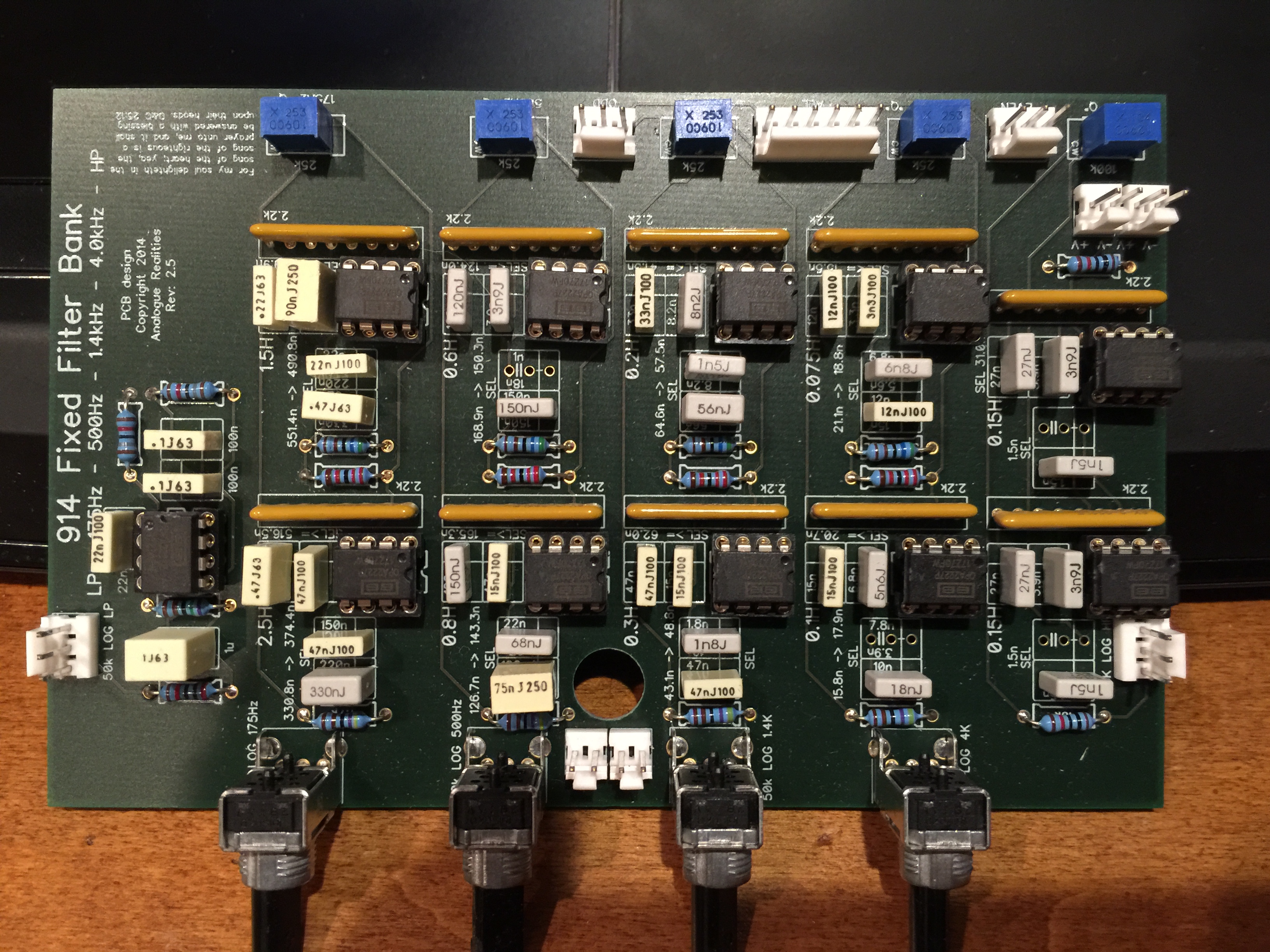
This is the middle “inductor” PCB. The 1.5nF capacitors in the HP cell on the right of the PCB should be pair of 1.0nF capacitors to make a combined 2nF. Do this in both stages. The LP cell is fine.

This is the top “inductor” PCB. There are no corrections to this PCB.
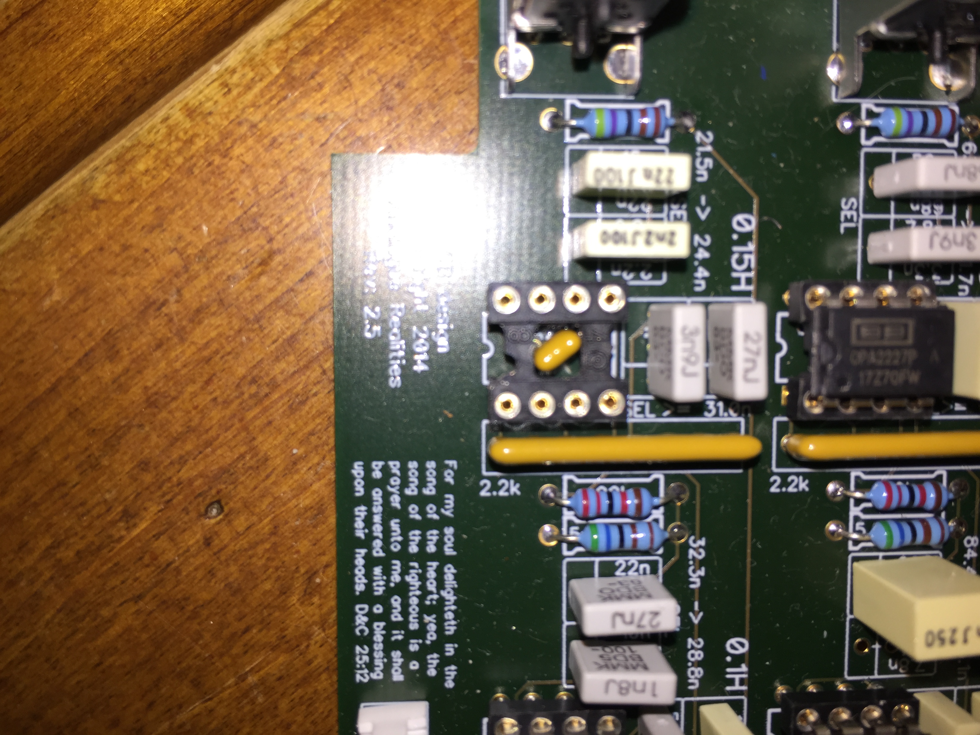
This photo just shows how I installed the decoupling capacitor in the middle of the IC socket.