Buy the PCB:
INITIAL COMMENTS:
DOCUMENTS:
Current Version 1.1:
The BOM changes depending on which module you are building, so check the module’s schematic and BOM for any additional components you may need.
INTRODUCTION:
One of the more interesting aspects of SDIY is the difference in power supply requirements. If you read my story, you know that my lack of understanding about power supplies was my stumbling block. Some of the PCBs need this daughter board and some have the conditioning on-board. I didn’t think I had the PCB real estate to incorporate the regulators and other components on some circuits, and I was trying to stay away from adding my own stuff to the original designs. In the end, this PCB is a weird compromise and on some of the smaller circuits, it was easier to incorporate this onto each PCB.
You don’t have to include this PCB if you already have the right supply voltages from a well regulated and filtered supply. It will come with each PCB set that needs, or could benefit from it. Some of Nyle’s designs (notably the VCOs) had some extra filtering for some parts or all of the circuit. This PCB accommodates the addition of these extra filtering elements if you want to add them. It has to supply outputs, + 12 and -10 volts, and a +V and -V line which come after any additional filtering Nyle added.
The PCB has room for two regulators, associated capacitors, trimmers to adjust the voltage output, an LED on each supply line for those who like blinky lights. I added the LEDS so the PCB could be built separately and trimmed. The regulators require a minimum current to start working and so the LEDs were a way to achieve the load before you hook it up. Please omit the LEDs if you want. They are an unnecessary current draw. More is explained below.
The PCB also allows you to fit this into either a MOTM™/Blacet™ +/- 15 volt system with the 4 pin big MTA connector, or a +/- 12 volt Doepfer™ system with a 10 pin header. I think the Synthasystem circuits will all work fine on a +/- 12 volt system. Remember though, that the discrete transistor circuits are biased for +12/-10 volts, not +/- 12 volts and trimming and/or function may have issues.
FUNCTION:
This module is an interface between you main power supply and various modules. It is a daughter board which attaches to the main module with standoffs. This configuration let me keep some measure of standardization between PCBs and allowed some of the deeper PCBs to be mounted parallel to the panels.
USE:
Inputs/Outputs:
This module has an input for the 4 pin, MTA 0.156 power connectors used on Frac modules, MOTM, etc. It also has a 10 pin Doepfer connector for the EuroRack users. It has two output jacks which are identical. They are to facilitate various module configurations and getting power to your PCB. If your main module PCB requires this PCB, build it and use it. Do not jury rig your power supply to the main module PCB. This PCB has short protection, decoupling and filtering that you will need. Especially on modules like the VCO which use straight +12/-10 as well as an additionally filtered +/- supply voltage.
Connect this to a good linear power supply with regulated outputs. You can configure the PCB to run from +/-12 VDC or +/- 15 VDC.
COMPONENT SELECTION:
See the Component Notes page for more information.
Resistors:
Just use a good quality resistor. Tolerance isn’t really an issue.
Capacitors:
There are probably a billion different ceramic capacitors at a place like Mouser. Pick a capacitor that can fit the hole easily, typically 0.1 inch on centers.
The 1.0 uF Tantalum capacitors can also be 10 uF Electrolytics. The data sheet for the LM317 and LM337 recommend either. You do need these to help prevent oscillation in the regulator. See the data sheets.
Capacitors should be 25 to 35 volts.
Inductors:
L1 and L2 are ferrite beads. You could also use PTC fuses, or whatever you generally use. The beads add some spike filtering.
You can use Mouser # 81-BL01RN1A2A2B
ICs:
The Power Regulation PCB is setup for LM317 and LM337 adjustable regulators. Since the power draw on all of these Steiner modules is relatively low, under 100 mA, I doubt you will need a heat sink. However, I tried to allow for a small snap on type heatsink or maybe a little bigger if you want one. The Frequency divider was rated at 100mA, Sequencer at 60mA, and triple EG at 70mA. The rest are below this. As the modules are built, I’ll try to test current draw.
For a heatsink, I’ve used an Aavid Thermalloy “snap-on” heatsink. Not huge, but it helps.
Mouser p/n: 532-576802B00
Mfgr. p/n: 576802B00000G
Diodes:
Nothing special, 1N4001s are fine. These provide a measure of reverse polarity protection.
Scenario 1: On the Power Regulation PCB they are placed before the regulators. In this scenario, you can probably omit them if you are installing a regulator on one or both sides of the supply. If you don’t use a regulator on one or both sides, the diode can help to mitigate damage from accidentally connecting the power supply backwards.
Scenario 2: On the PCBs with the power regulation on the main PCB, scenario 2, they are placed after the voltage regulators. If you are regulating either the positive or negative voltage, these diode are pretty much useless. If you don’t regulate one or both sides of the supply, the diode can help to mitigate damage from accidentally connecting the power supply backwards.
Trimmers:
Use good trimmers, please. A good Bourns multi-turn trimmer like Bourns 3296Y series will fit the pad layout and work well.
Jacks:
No jacks, just use the standard 0.156 4 pin MTA for the Frac/MOTM and a 0.100 10 pin header for the Doepfer. You can fit the boxed in polarized Doepfer header if you want. Just make sure you install it properly.
BUILD NOTES:
Soldering:
I assume you know the basics of soldering. I like to insert the low lying parts first, like resistors, diodes, etc. After these, I install the IC sockets. Next capacitors, transistors, connectors. Use a good solder, either an organic flux, which you should wash regularly, or a no-wash flux.
Take a break every so often, wash off the flux if you are using a flux which required cleaning. Double and triple check orientations, pins, and solder joints.
Power Supply Regulation/Filtering:
Build this PCB first and get the regulators (if you use them) trimmed to +12/-10 volts.
R2, R6, C4, and C8 are installed on certain modules which use extra filtering to help with noise. The VCF and VCO are among these. The project pages will tell you if you need these components or if they can be omitted.
Some additional comments here. These modules will be tested to run on +/-12 VDC and the individual project pages will tell you if it runs on +/-12 or if you need to have the -10 VDC.
I asked Nyle why the unbalanced supply in the original Synthasystem. Turns out it because of how Nyle designed the -10 volt section of the power supply, not for any magical requirement to have -10 volts.
With that said, the power/regulation PCB has 2 voltage regulators on it which can be set to +12/-10 (or +/-12 volts) depending on your needs. If you are coming from +/-15 volts, you need both regulators and you may as well set one to -10 volts.
If you are coming from +/-12 volts, technically you don’t need the regulators, but if you want, install the negative one and set it to -10 volts. When this board is not connected to the main VCO PCB, you have to have a minimal load in order for the regulators to regulate, that’s the purpose of the LEDs. you can install these for fun if you want, but are not needed if you don’t use the regulators.
Important… if you don’t install the regulators, you have to install a jumper between pins 2 and 3 as shown on the Power/Regulation PCB or you won’t get power to your module.
If you are a EuroRack person with +/-12 VDC coming in, you could choose to not install the negative regulator, but I still recommend using +12/-10 VDC as the bias resistors are all setup for this unbalanced power supply.
Nothing else special.
Mounting:
This PCB has four holes to allow flexible mounting configurations. This board was meant to mount at the same edge as the mating connector on the main module board using spacers in two of the holes. There are two power outputs so that, for example, on the Triple Envelope Generator which has 3 EG PCBs and possibly a trigger converter, you have some extra places to connect power.
Calibration:
To calibrate, turn the trimmers to mid rotation and connect your power supply cord to the appropriate connector. If you didn’t install the LEDs, connect the output to a resistor. You need 5 to 10 mA being drawn from the regulator before it will regulate.
This PCB is included when/where needed.
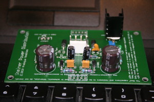
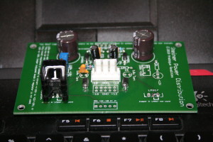
The below images show a typical Power/Regulation PCB. This one is configured for +12 and -10 Volts. Only the -10 volt regulator and associated components are installed. This one is also configured for the VCO, so it has the extra filter capacitors (150u) and resistors (22 ohm for the VCO). There is also a small snap on heatsink, the one described in the project build notes. The -10 volt regulation is solid between -12 and -18 volts.
Note the jumper where the +12 volt regulator goes.


