

Before You Buy
Before you buy this PCB, please get hold of me:
dingebre
at
3dphysics
dot
net
The PCB works, and is a fun little project. That said, there are much better ways to match transistors.
These PCBs were made more to honor how Moog matched their transistors than to be the “best” way to do it. This circuit works, don’t misunderstand, there are just other ways. For my part, if I need a match pair, I try to use a monolithic pair on an IC. Otherwise, I’ve used my Peak DCA Pro transistor tester. I think it did fine for the applications I had. I’ve also used the Moog circuit and my PCB.
Below are links to two documents with different approaches that can be built on “vero” board. The first is an excellent way designed by Ian Fritz. The other is just another interesting way. I haven’t studied it nor do I have any idea how well it works. Ian’s is a great method.
Disclaimer:
All external links are provided as a service and courtesy. Unless otherwise noted, listing of a link here in no way implies an endorsement or recommendation, of the site, products sold, or any material on the site, in particular links, statements, or opinions. Continue to these sites at your own risk. By following a link you acknowledge an understanding that the content is beyond the control of Analogue Realities and Analogue Realities cannot be held responsible for any harm or damage from clicking through on a link.
I assume you understand this is a web and at some point, you will follow enough links to end up at some site which has truly reprehensible content. If you get to a site that you think I should delete, let me know and we can discuss it.
Be safe as you surf, please.
- Get a virus, mal-ware, ad-ware detection and eradication program and use it.
- Don’t give out any personal information unless you trust the site and the process (I use PayPal because I don’t want your credit card or other information).
Even the best maintained sites are subject to hacking and the introduction of mischievous scripts, so be careful.
So, now on to my PCBs. I recommend that you solder wires to the spot where the transistor to be matched goes. I used these from Adafruit. Moog doesn’t seem to offer them anymore.
I am not associated with Adafruit other than being a happy customer.
Adafruit breadboard wires
You will notice there are two different pinouts for the NPN transistors. I had originally thought I’d just push the transistor to test into the PCB and I had a bunch of NPNs with an ECB pinout rather than the more typical EBC. Don’t put two transistors into the holes at once and if you use the extension leads, just solder them into one of the locations.
I would also mount the PCB on some nylon standoffs to keep it off your workbench. Then, take a bunch of transistors and put them into a breadboard, something like the one below or hundreds of others from other vendors, using needle nose pliers on the leads to insert them:
Adafruit breadboard
Let them stabilize for a while, like an hour or so (even touching them with your finger can affect the measurement). Then hook up your meter, and plug the wires into the breadboard to the desired transistor. Take you reading really fast before the transistor heats up. Then move on to the next one.
I’m including some documents such as they are. You probably don’t need the ferrite beads, you can just use a jumper wire. You can install either the 4 pin MTA connector for a typical MOTM 15 volt supply or the smaller 10 pin Doepfer 12 volt header. There are two, two pin headers labeled NPN with a “+” and PNP with a “+”. These are where you connect your meter.
Buy the PCB:

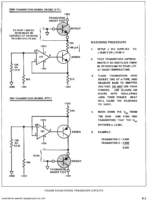
FUNCTION:
This is a Moog™ circuit used to match the characteristics of two transistors for use where such a pair is required. VCO core comes to mind.
USE:
In the course of building a synthesizer, a pair of transistors with similar electrical characteristics is often required to help stabilize temperature fluctuations, such as in a VCO core. Some use them in other spots, but they are not necessarily needed, but it also doesn’t hurt. In the Synthasystem, the only place such a pair is required is in the VCO core, although Nyle confessed to me that in later production, they stopped matching them. I do, however, have a very vivid memory of matching transistors while working for Nyle, and a special drawer with matched pairs taped together.
In the resurrection of the Synthasystem, there are a lot of “paired” transistors in various modules, notably the VCO and VCF. I chose for no real reason, to use a footprint compatible with most monolithic paired transistors but which will also work with discrete transistors. In the Steiner VCO core, you also have to have a PNP transistor in thermal contact with the matched NPN pair. This PNP does not have to match the NPNs. I don’t really know a good way to match a PNP to a NPN anyway.
To use this PCB, you need a volt meter with milli-volt precision and accuracy or better. I recommend you solder some wires to the “transistor to match” locations on the PCB with a small piece of solid wire, or other pin on the free end of each wire. There are some mini patch cables made for bread boards that are great for this as they already have straight solid pins on each end. cut them in half and solder one end to the PCB. Moog™ has some for their Werkstatt synthesizer, Adafruit has them, too.
Next, line up a bunch of transistors on a bread board and let them stabilize in temperature. Take the three leads you just soldered and connect the free end to the breadboard where the first transistor is and measure the voltage at the output. Note the voltage and go to the next transistor. When you have two transistors with a voltage within 2mV, you have a good pair.
Here is the original Moog™ schematic with the unsurprising error of a missing resistor between the two transistors on the PNP side, sigh. You need a 10K resistor on the PNP matching circuit comparable to the NPN circuit; between the two transistors.
Inputs/Outputs:
The PCB has power input, +/- 12 or 15 volts. It has two output connectors, one for the NPN and one for the PNP voltage. Put something here that will make it easy to connect a volt meter.
GENERAL CONNECTIONS:
COMPONENT SELECTION:
See the Component Notes page for more information.
ICs:
Any decent OpAmp is fine.
Transistors:
Any small signal transistors can be used.
BUILD NOTES:
Soldering:
I assume you know the basics of soldering. I like to insert the low lying parts first, like resistors, diodes, etc. After these, I install the IC sockets. Next capacitors, transistors, connectors. Use a good solder, either an organic flux, which you should wash regularly, or a no-wash flux.
Take a break every so often, wash off the flux if you are using a flux which required cleaning. Double and triple check orientations, pins, and solder joints.
Power Supply Regulation/Filtering:
Any balanced power supply can be used, +/-12 to +/-15 volts.
COMPONENT PLACEMENT:
Mounting:
There are four holes which are sized for the snap in end of these spacers, Eagle Products #561-MTP250. These don’t seem to be available at Mouser anymore, but any spacer with snap in on the end should work.